
Design for the Printer You Own, Not the Render You Love
Posted by SFL Designs on Oct 29th 2026

A beautiful Fusion 360 model can still be a terrible print.
The render does not care about gravity. The nozzle does.
Design for manufacturing means the manufacturing method gets a vote while you are modeling. For fused deposition modeling (FDM), the usual spool-fed printing process, that means layers, overhangs, bridges, supports and orientation belong in the design conversation before you export the STL.
This does not make the model boring. It makes the print less dramatic, which is better.
Choose the print orientation before the part is finished
Orientation is not a slicer decision you postpone until the end. It affects strength, surface quality, support material, print time and dimensional accuracy.
Start a Fusion 360 design by asking which face should sit on the build plate.
Look for:
- a stable flat base;
- the fewest important surfaces facing downward;
- layer lines that support the real load instead of peeling apart;
- holes and mating surfaces that print cleanly in that direction;
- a reasonable part height and footprint.
No orientation wins every category. The job is to choose the best compromise on purpose.
If the most important load pulls across layers, redesign the feature or change orientation while the model is still easy to edit.
Overhangs need something under them
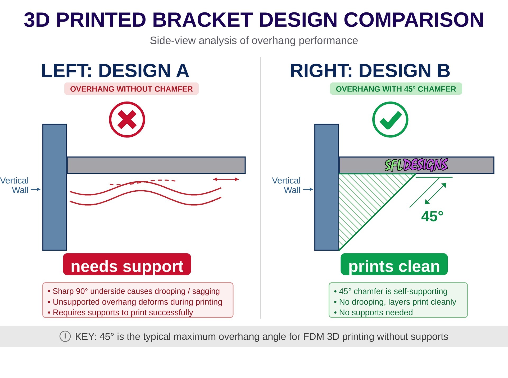
Each new line of plastic needs support from the previous layer. A sloped wall can step outward a little at a time. A flat ceiling tries to place a line over open air.
The familiar “45-degree rule” is a useful starting heuristic: many printers handle a slope around 45 degrees from vertical without separate support. It is not a law. Nozzle size, layer height, cooling, material, speed and feature length all affect the result.
Use a real overhang test for your machine and material. Then design inside the range you can repeat.
Replace the ugly underside with a chamfer
Suppose a shelf sticks straight out from a vertical wall. The underside begins as a 90-degree overhang and may need support.
In Fusion 360, use Modify > Chamfer on the lower edge to create a sloped transition. A 45-degree chamfer is a common support-friendly starting point. It also spreads the connection over more area instead of meeting at one sharp inside corner.
Do not add a chamfer because somebody said chamfers are good. Add it because it creates a printable path and supports the load.
A fillet can also reduce stress, but a downward-facing fillet may begin with a steep overhang. Check the section and the slicer preview. The prettier Fusion surface is not always the happier toolpath.
Bridges are useful, but they are not invisible floors
A bridge is a strand printed across a gap with support at both ends. Short bridges can print cleanly when cooling and material cooperate.
Long bridges sag. Wide bridge areas multiply the risk. Critical mating surfaces rarely improve after hanging in the air.
If a bridge matters, test that span on the real printer. If the underside must be precise, change orientation, split the part or redesign the opening into a self-supporting shape.
For example, a horizontal round hole has a steep ceiling. A teardrop-shaped top or a small flat at the peak can make the opening easier to print without filling it with support.
Split the part when one-piece pride stops helping
“One piece” sounds elegant. Sometimes it is just stubborn.
Fusion 360 gives you tools such as Modify > Split Body to divide a model into printable sections. Add locating pins, tabs, dovetails or screw features so the pieces align during assembly.
A split can:
- place each section in a stronger orientation;
- eliminate a large support forest;
- improve the visible surface;
- fit a part onto a smaller printer;
- make a failed section cheaper to reprint.
The joint becomes part of the design, so give it deliberate clearance and enough material. Do not slice the body in half and expect glue to handle the meeting agenda.
Or build the support in, as a breakaway
There's a middle path between “the design needs no support” and “let the slicer grow a forest”: design the support yourself, as a breakaway feature. A breakaway feature is a sacrificial piece of the model (a thin prop, tab, or membrane under the one surface that truly needs holding up), connected by a deliberately small contact area or a tiny gap, so after the print it snaps or peels away cleanly and takes its scar with it.
Why design it instead of letting the slicer do it? Control. You choose exactly where it touches, how big the contact patch is, and where the break line lands, usually hidden on a face nobody sees. Slicer supports are a general-purpose guess. A designed breakaway is placed like you meant it, because you did.
Rules of thumb: keep the contact small and weak on purpose; put the break line where a faint witness mark won't matter; and test the break on a small piece first. A breakaway that needs pliers and prayer is just a support with extra steps.
Model a tiny manufacturing test first
Before committing to a long print, isolate the risky feature in Fusion 360.
Create a small test piece containing the real chamfer, bridge, hole, snap or joint. Print it in the intended material and orientation. Measure it. Flex it. Assemble it.
That test answers the question you actually care about, while a calibration cube mostly proves you can make a cube.
Shop note: The best support is the support you remove from the design before slicing.
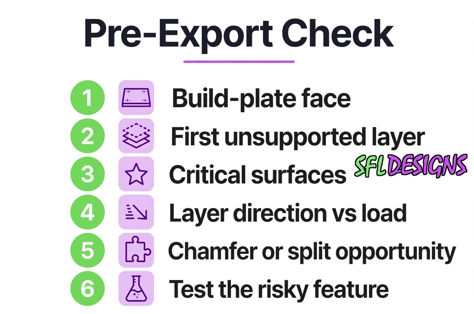
Use this pre-export check
Before sending the model to the slicer, ask:
- Which face is the intended build-plate face?
- Where does the first unsupported layer appear?
- Which surfaces must look good or fit accurately?
- Does the layer direction suit the real load?
- Would a chamfer, bridge-friendly opening or split body remove support?
- Have I tested the feature that is most likely to fail?
Designing for the printer is not lowering your standards. It is acknowledging how the part becomes real.
The render gets the applause. The toolpath has to do the work.
— Jason, SFL Designs
From our workbench to your display — print it, mount it, light it up.