
Walls Beat Infill More Often Than You Think
Posted by SFL Designs on Oct 27th 2026

“Just make it 100% infill” is the 3D-printing version of fixing a chair with more chair.
Sometimes a solid part is appropriate. Often it is extra time, extra material and extra confidence without a clear reason.
For many functional prints, the outer walls (also called perimeters) do a large share of the work. They form the continuous shell that resists bending, protects edges and defines holes and fastener features. Infill supports those walls and carries load through the interior, but it does not automatically deserve the starring role.
First, know what the slicer is building
A slicer turns the model into toolpaths, the lines the nozzle will actually print.
- Walls or perimeters are the loops around the outside and around internal holes.
- Top and bottom layers close the shell.
- Infill is the internal pattern between those surfaces: the grid, triangles or squishy honeycomb-looking pattern called gyroid.
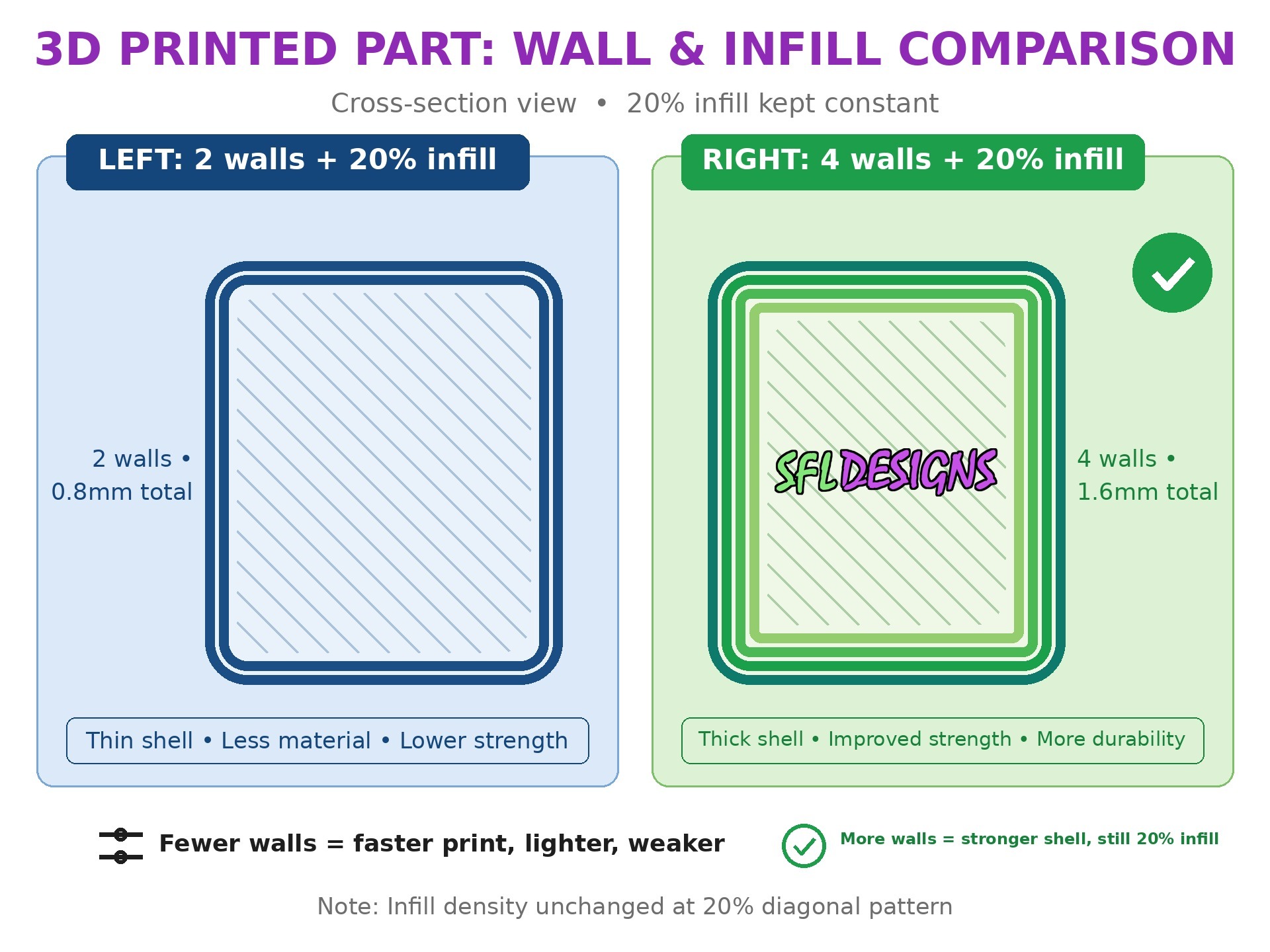
When you raise infill percentage, you pack more internal lines into the part. When you raise wall count, you thicken the continuous shell.
Those changes do different jobs.
One pattern note while we're here, because it matters more than the percentage debates: which pattern you pick changes how the nozzle treats your print. Grid is the classic default, and it's strong, but grid lines cross each other in the same layer, so the nozzle drags back over filament it already laid down. That dragging can tear little gaps in the extrusion, build up cooked plastic on the nozzle, and on a bad day knock a print into a layer shift. Gyroid and honeycomb don't cross themselves that way (the nozzle keeps flowing instead of plowing through its own work), and both are strong and quick to print. They're what I reach for by default; grid is what I talk people out of.
Put material near the outside when bending is the problem
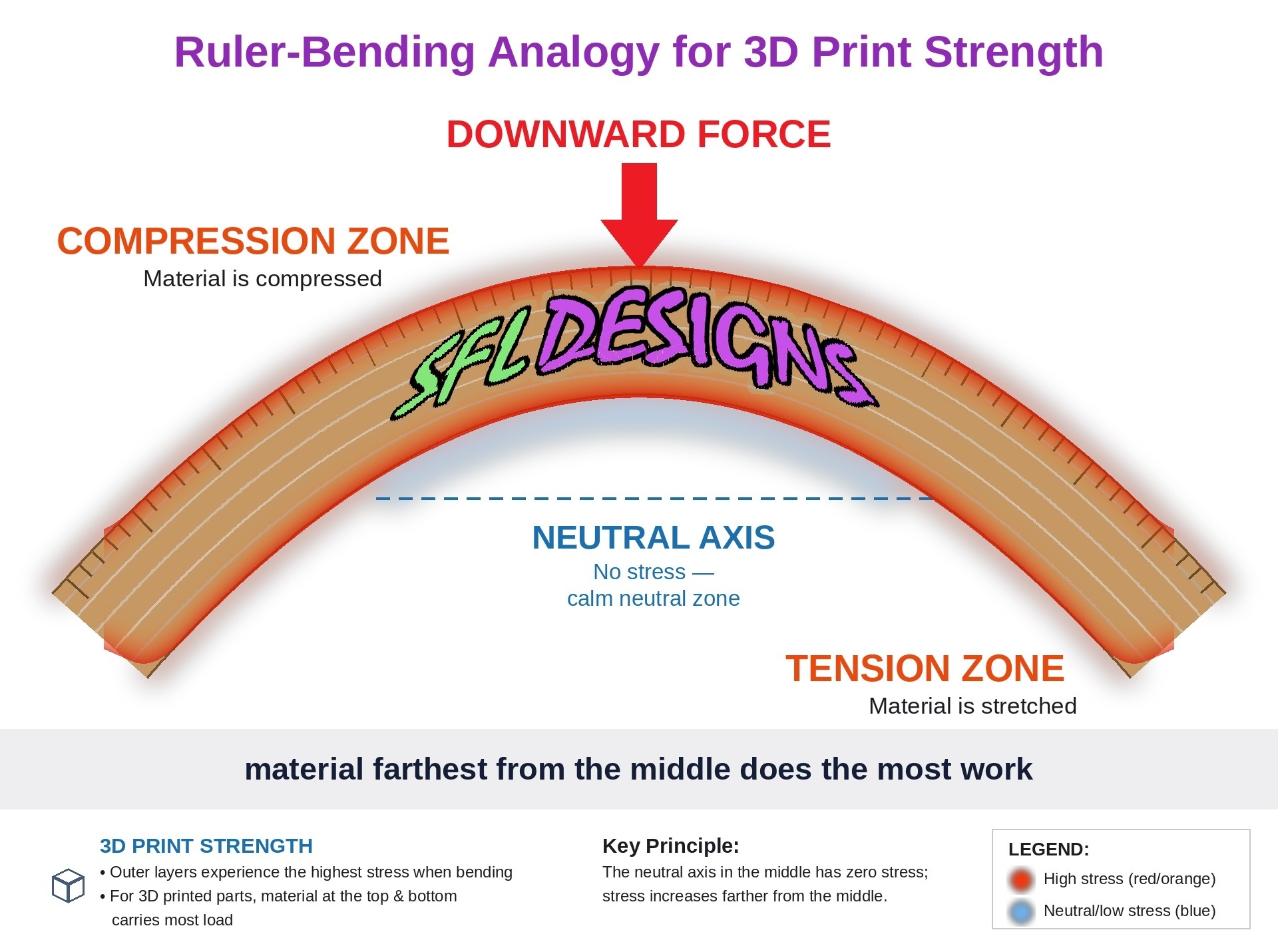
Think about bending a ruler. The material near the outer faces travels through the largest tension and compression. The center matters, but material farther from the middle has more leverage against bending.
That is why a hollow tube can be surprisingly stiff for its weight, and why adding walls can improve many brackets, clips and mounts efficiently.
This is not permission to use 2% infill everywhere. The interior still keeps walls supported, connects features and resists crushing or local loads. The point is to stop treating infill percentage as the only strength control.
Read the layer preview before adding plastic
After slicing, switch to the layer or toolpath preview. Look at the actual paths.
Ask:
- Are there enough continuous walls around the loaded edge?
- Does a screw hole have real material around it, or one thin loop and hopeful infill?
- Is a narrow feature filled with useful lines, or is the slicer skipping awkward gaps?
- Do the top layers have enough support from below?
- Is the load crossing a weak layer direction no matter how much infill you add?
The preview is the truth. The solid model is only the request.
Shop note: If a feature matters, inspect how the slicer plans to build it. Do not assume the inside looks the way your imagination drew it.
More infill cannot fix bad orientation
Fused deposition modeling (FDM) prints are direction-dependent. A part can be strong along a continuous extrusion path and weaker where the load tries to separate layers.
If a hook is oriented so the main load peels layers apart, 80% infill may produce a heavier version of the same bad idea.
Rotate the part if that improves the load path. Change the geometry. Add a radius where stress concentrates. Thicken the feature where it connects. Then use walls and infill to support that design.
Material settings are not a substitute for load-path thinking.
Use local reinforcement when the slicer supports it
Many slicers offer modifier regions: selected areas where you can increase walls, infill or another setting without changing the whole part.
That can be useful around a fastener boss, a loaded corner or a narrow connection. You reinforce the area doing the job instead of filling every quiet corner with plastic.
The names and steps vary by slicer, so use the feature only after checking the preview. A modifier that misses the intended layers is decorative paperwork.
Start with a controlled test
If a part keeps failing, do not jump from 20% to 100% infill and call it engineering. Print two or three small versions with one change at a time:
- the current setup;
- more walls with the same infill;
- a different orientation or reinforced geometry.
Break or load them in the same way. Record where they fail.
The failure location tells you more than the infill number. If the crack begins at a sharp corner, fix the stress concentration. If the layers peel, revisit orientation and temperature. If a thin wall buckles, add shell thickness or improve the shape.
The practical rule
For a functional print, start by giving the shell, holes and loaded features enough real material. Use infill to support the structure and suit the load, not as a volume knob labeled “strength.”
Then test the actual part in the actual direction it will be used.
Strong prints do not come from one heroic percentage. They come from geometry, orientation, extrusion and material all agreeing on the job.
— Jason, SFL Designs
From our workbench to your display — print it, mount it, light it up.